
The hardware behind the first honeypot was nothing exotic. It was an ESP32-S3 development board mounted in a screw-terminal breakout board. The ESP32 gave me Wi-Fi, enough memory to run the project, and a platform I could keep changing as I learned more.
The earliest version created its own test Wi-Fi network and presented itself as a small network device. Later, I moved it onto an isolated Wi-Fi network of its own. That was important. A honeypot is supposed to attract activity, so it should never have a clear path back to computers, files, or other devices that matter.
The ESP32 did not run a real operating system or give anyone a working command shell. It offered low-interaction services that looked interesting enough to receive traffic and record what reached them. The final version included web and IP-camera bait, along with listeners for Telnet, FTP, SSH, and Android Debug Bridge traffic.
Each service had strict limits. The SSH listener collected the opening client banner but did not perform a real SSH login. The web service could record requests and attempted logins, but it did not provide access to the device. Upload attempts were identified and logged without saving the submitted file.
The useful part was the record it created. Events followed the same basic structure: which service received the connection, what action occurred, the source address, and details such as a requested path or user agent when they were available. A private dashboard showed the recent activity, and a separate notification helper could alert me when selected events occurred.
At first, I mainly wanted to know whether anyone would notice the device. Once it was reachable, that question did not take long to answer. Automated probes began finding it, and the event history started showing which services and paths they were looking for.
That changed the project. The ESP32 was no longer just a board I had programmed. It had become a small observation point that could show me how quickly an exposed device gets scanned and how repetitive much of that activity is.
The board in the photograph is the final version of that original hardware. The software changed several times, but the basic idea stayed the same: keep the system small, keep it isolated, and record enough information to understand what was knocking on the door.
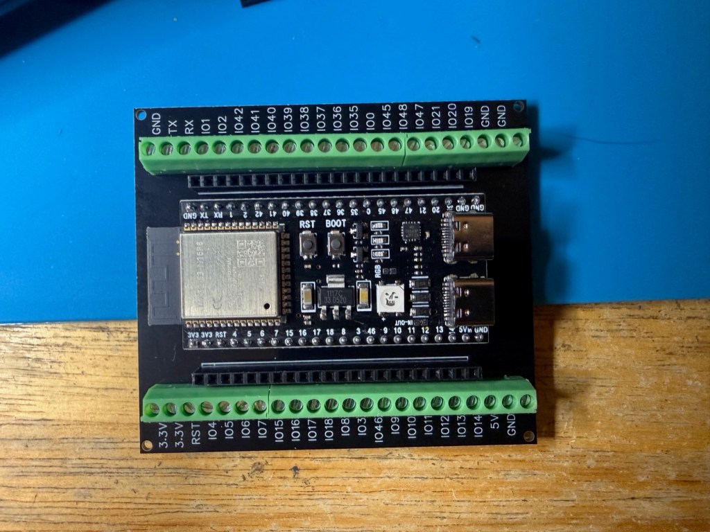
Here’s the Hardware used for this project:
ESP32-S3 development board: https://www.amazon.com/dp/B0GVSD9LJB
Screw-terminal breakout board: https://www.amazon.com/dp/B0GFP5Q122
Note: The antenna is irrelevant to the project. They just happen to come with it.
In the next post, I’ll share the complete Arduino sketch that ran the final ESP32 build. I’ll also show examples of the activity it recorded and how those raw connection attempts became something I could investigate and report. The code will be included in a copyable block for anyone who wants to study it or adapt it for an isolated lab of their own.


Leave a Reply